Up and Down Garage Doors diagnoses and repairs photo eye wiring failures across Metro Vancouver — polarity reversals, staple-cut insulation, corroded splices, and LED status misreads — using trade-standard 22 AWG solid conductor specifications and manufacturer-verified alignment protocols.
Garage Door Photo Eye Wiring Guide
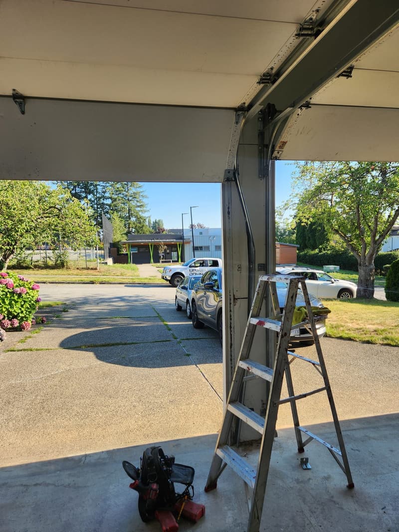
Metro Vancouver’s housing mix — 1960s split-levels in North Delta, 1980s ranches in Surrey, 2000s townhomes in Coquitlam, and post-2010 infill in Richmond — creates distinct wiring failure patterns. Pre-1990 homes typically run 22 AWG solid copper (0.64 mm diameter) in white CL2 jacket stapled to roof trusses; the staples crush insulation against Douglas fir framing after 20+ years of seasonal humidity cycling. Post-2000 builds often use 22/4 stranded (7×30 AWG) for multi-sensor runs, but the thinner individual strands fatigue at sharp bends near header brackets. Coastal rain penetration at unsealed wall penetrations accelerates copper oxidation, raising resistance above the 4-ohm maximum most LiftMaster and Chamberlain logic boards tolerate.
Polarity: How to Identify and Verify Correct Wiring
What colour is positive on a garage door sensor wire?
Standard industry convention: white/red stripe or solid white = positive (+), white/black stripe or solid black = negative (−). LiftMaster 41A5034 and Chamberlain 41A4373A photo eyes follow this scheme. However, Metro Vancouver installers frequently reverse pairs at the opener terminal block when both conductors are white. Verify with a multimeter set to DC volts: place red probe on the sensor’s white/red terminal, black probe on white/black; you should read 5–7 VDC when the opener is powered. Reverse the probes — reading should be negative. If you measure 0 V or reversed polarity at the sensor head, the pair is swapped at the opener.
Can reversed polarity damage the photo eyes?
Reversed polarity on 5 VDC sensor circuits rarely causes permanent damage — the IR LED simply won’t emit, and the receiver stays dark. The opener logic board will show “sensor error” or flash codes (e.g., LiftMaster 8500W: 4 flashes = misaligned/obstructed; Chamberlain MyQ: solid amber on sender, off on receiver). Correct the polarity at the terminal block; no component replacement needed unless wires were shorted during miswiring.
Staple-Cut Insulation: Diagnosis and Repair
How do I know if a staple cut the sensor wire insulation?
Symptoms: intermittent “door reverses” on sunny days (expansion closes the nick), consistent failure after rain (water bridges the cut), or opener LED flashing “shorted sensor” (LiftMaster 8550: 1 flash). Inspect the wire run where it passes over truss plates or through ⅜″ holes in header joists — staples driven at an angle slice the 0.4 mm PVC jacket. Use a non-contact voltage tracer or continuity test: disconnect both ends, short one end, measure continuity at the other. Infinite resistance = open circuit from a severed conductor; low resistance to ground = staple nick contacting framing.
What is the proper repair for a staple-damaged sensor wire?
Do not tape over the nick — seasonal movement will reopen it. Cut out the damaged 300 mm section. Splice using gel-filled butt connectors (3M UY2 or equivalent) rated for 22–24 AWG solid/stranded. Strip 6 mm of insulation, insert each conductor fully, crimp with ratcheting tool (not pliers). Slide the gel cap over the crimp; the hydrophobic gel prevents moisture ingress. Secure the repaired run with plastic cable clamps (not staples) spaced 450 mm per CEC 12-510, keeping 50 mm clearance from sharp edges.
Splicing Techniques for 22 AWG Sensor Wire
What gauge wire is used for garage door sensors?
22 AWG (0.64 mm solid or 7×30 AWG stranded) is the universal standard for residential photo eyes — LiftMaster, Chamberlain, Genie, and Linear all specify 22 AWG CL2 or CL3P. Maximum run length: 180 m (600 ft) total loop for 5 VDC circuits; voltage drop exceeds 0.5 V beyond that, causing false obstructions. For runs over 100 m, some installers upsize to 18 AWG (1.02 mm) but must verify terminal block acceptance — most opener headers only accommodate up to 20 AWG.
Can I splice sensor wire with wire nuts?
Wire nuts are not rated for 22 AWG solid conductors — they cannot achieve gas-tight connection on such small diameters. Use gel-filled butt splices (3M UY2, Scotchlok UR2) or solder with heat-shrink tubing (3:1 adhesive-lined). Solder joint resistance must stay under 0.1 Ω; verify with 4-wire Kelvin measurement. All splices must reside in accessible junction boxes (CEC 12-3010) — never buried in insulation or behind drywall.
LED Status Meanings Across Major Brands
What do the LED colours mean on LiftMaster photo eyes?
LiftMaster/Chamberlain (Security+ 2.0, MyQ): Sender (amber LED) = powered, emitting IR. Receiver (green LED) = aligned, receiving signal. Both solid = normal. Sender flashing = wiring fault (open/short). Receiver flashing = misaligned or obstructed. Both off = no power (check opener terminal block voltage). Legacy Security+ (pre-2011): Sender red, receiver green — same logic.
What do Genie and Linear sensor LEDs indicate?
Genie Safe-T-Beam (STB): Sender red solid = OK; red flashing = wiring fault. Receiver green solid = aligned; green flashing = misaligned/obstructed. Linear/MegaCode: Single bi-color LED on receiver — green = aligned, red = obstructed, amber = wiring fault. Always confirm with the specific model’s installation manual; LED behaviour changed across firmware revisions.
Metro Vancouver Environmental Factors
Coastal humidity (annual average 75–85 % RH) accelerates oxidation at every splice and terminal. Salt-laden air within 2 km of Georgia Strait or Burrard Inlet (Richmond, Tsawwassen, West Vancouver, White Rock) cuts connector lifespan in half — expect 7–10 years versus 15+ inland. Winter condensation in unheated garages drips onto header-mounted terminal blocks; dielectric grease (Permatex 22058 or equivalent) on all screw terminals prevents green corrosion powder that raises resistance. UV exposure on south-facing garage facades embrittles white CL2 jacket in 8–12 years; replace with UV-rated CL3P (black jacket) during rewires.
FAQ
How do I test if my photo eyes are getting power?
Set multimeter to DC volts. At the opener terminal block (usually labelled SENSOR or 1/2/3), measure between common and sender terminal — should read 5–7 VDC. Then measure at the sensor head terminals. Voltage drop over 0.5 V indicates undersized wire, corrosion, or a staple nick.
Can I run sensor wire in the same conduit as opener power wires?
No. CEC 12-906 requires Class 2 circuits (sensor wiring) to be separated from Class 1 (120 V opener power) by at least 50 mm or a continuous barrier. Inductive coupling from motor start-up transients induces false signals in 22 AWG runs.
Why does my door reverse only in the afternoon?
Thermal expansion of the garage header bows the sensor brackets 1–2 mm out of alignment. Combined with staple-nicked insulation that shorts when warm, the receiver loses signal. Realign brackets with slotted holes; replace damaged wire section.
Do I need to replace both photo eyes if one fails?
Replace as a matched pair. Sender and receiver are calibrated together; mixing generations (e.g., Security+ sender with MyQ receiver) causes intermittent alignment faults. LiftMaster 41A5034 kit includes both heads, brackets, and 30 ft of 22/2 wire.
What is the maximum wire length for garage door sensors?
180 m (600 ft) total loop for 22 AWG at 5 VDC. Beyond that, voltage drop exceeds spec. For detached garages with longer runs, use 18 AWG or install a powered repeater module (LiftMaster 850LM) at the midpoint.
Need Professional Sensor Wiring Repair in Metro Vancouver?
Up and Down Garage Doors traces and repairs photo eye wiring faults across Richmond, Vancouver, Surrey, Burnaby, Coquitlam, Delta, Langley, and White Rock. We use gel-filled splices, UV-rated CL3P wire, and dielectric grease on every terminal — built for coastal BC conditions. Call 778-873-7282 for same-day service.
Up and Down Garage Doors | Richmond Garage Door Repair | LiftMaster 8500W Service | Opener Repair | Contact Us